Arc flash study report · IEEE 1584.1-2022 · NFPA 70E 2027
What an arc flash study report must contain. And what to do if yours does not.
Eleven sections, mapped to IEEE 1584.1-2022. Open the VB Arc360 brochure, no form. Or request the free review: a VB engineer sends you a full sample report and tells you, in writing, what yours is missing. Two business days.
1,000+ assessments21 countriesSince 2014Signed by an engineer
Free arc flash report review
Request the free review. A VB engineer emails you a full sample VB report and a secure link to send the report you hold. Written verdict against the 11 sections in two business days. Short form, no phone number.
Your report is read by an engineer under confidentiality and deleted after the verdict unless you ask us to keep it.
Trusted on plants that cannot stop











- 0sections IEEE 1584.1 expects in the deliverable
- 0maximum age before the report must be redone
- 0arc flash assessments delivered
- 0assets twinned and labelled
- 0countries, one signed report
How the free review works
- 1
Request the review
Fill the short form. A VB engineer replies with the sample report and a secure link to send the PDF you were given, however old.
- 2
An engineer scores it
Against the 11 sections below: present, partial or missing, with the clause each one satisfies.
- 3
Get a written verdict
One page, two business days: what is missing, whether the study can be reused, and what a reassessment would cover.
The deliverable
What does an arc flash study report contain?
A complete arc flash study report contains 11 sections: a conformance matrix against NFPA 70E 130.5, NEC 110.16 and the client specification; an executive summary; the calculation method and assumptions per IEEE 1584-2018; the one-line diagram reconciled to the as-found plant; the field data pack; short-circuit results; protective device coordination; the bus-by-bus incident energy table; the label schedule with artwork; the action register; and the certification required by 29 CFR 1910.132(d). IEEE 1584.1-2022, the guide that specifies the deliverable, expects every one of them.
| # | Section | What it must contain | IEEE 1584.1-2022 topic | Check in your report |
|---|---|---|---|---|
| 1 | Conformance matrix | Every clause of NFPA 70E 130.5, NEC 110.16 and the client or insurer specification, mapped to the page that satisfies it | Scope and references | Is there one? Most reports open with a cover letter instead. |
| 2 | Executive summary | Buses studied, PPE category distribution, buses above 40 cal/cm², the five actions that matter, in two pages | Summary of results | Can your EHS head read it without an engineer? |
| 3 | Methodology and assumptions | IEEE 1584-2018 declared, electrode configurations, utility fault contribution source, software named, every conservatism listed | Methodology · assumptions · software | Does it say where the utility fault current came from? |
| 4 | One-line diagram, as found | Walked down, drift from the legacy drawing logged, co-signed by the site engineer, nomenclature matching the tables | Updated single-line diagram | Is the one-line dated after the walkdown, or before it? |
| 5 | Field data pack | Nameplates, CT and PT ratios, trip-unit settings, cable lengths, photographs per equipment item | Input data documentation | Can you find the trip settings for any breaker in five minutes? |
| 6 | Short-circuit study | Bolted and arcing fault current at every bus, equipment ratings checked against duty | Short-circuit results | Is any bus flagged over duty? If none, ask why. |
| 7 | Protective device coordination | Time-current curves per circuit, miscoordination identified, settings recommended | Time-current analysis | Are TCC plots present, or only a settings table? |
| 8 | Incident energy table | Per bus: voltage, working distance, clearing time, incident energy, arc flash boundary, PPE category, worst-case operating scenario named | Results table · operating modes | Does every row name the scenario that produced it? |
| 9 | Label schedule and artwork | One line per label with the four NEC 2026 elements, assessment date on the artwork, installation photographs | Labelling | Is the date on the label artwork? |
| 10 | Action register | Engineering controls, settings changes, PPE, procedure, training: ranked, owned, dated | Recommendations | Does each action have an owner and a date? |
| 11 | Certification and signatures | Written hazard assessment certification (29 CFR 1910.132(d)), engineer of record signed, PE stamp where required, review date | Advisory on system changes | Is a named person accountable for the numbers? |
IEEE 1584.1-2022 is the IEEE guide for the specification of scope and deliverable requirements for an arc flash hazard calculation study. In plain terms: the list a buyer can hold a vendor to. Most reports in circulation were written before it existed.
Section 8
How do you read the incident energy table?
Read one row at a time: the bus, its voltage, the working distance the figure applies to, the clearing time, the incident energy in cal/cm², the arc flash boundary, the PPE category, and the operating scenario that produced the worst case. A row with no working distance or no scenario cannot be checked and should be questioned. Anything above 40 cal/cm² is work that is de-energised or not done.
- Working distance missing: the cal/cm² figure has no meaning
- Scenario not named: you cannot tell if it was utility, generator or bypass
- Clearing time of 2 s on many rows: the arc duration cap was hit, the number is a floor not a result
- No DC buses: the UPS and battery rooms were never studied
- Every PPE category reads 2: the table method was used, not a calculation
- Boundaries in the table do not match the labels on the panels
Incident energy table · worked excerpt
| Bus | kV | Scenario | Ei cal/cm² | AFB | PPE |
|---|---|---|---|---|---|
| MV switchgear | 13.8 | Utility max | 8.4 | 62 in | 2 |
| Main switchboard | 0.48 | Utility max, ST 0.3 s | 31.7 | 128 in | 4 |
| PDU 3A | 0.48 | UPS bypass | 6.2 | 48 in | 2 |
| UPS battery string | 0.54 DC | Battery EOL | 3.9 | 36 in | 1 |
| ATS-1 | 0.48 | Default settings | 44.6 | 150 in | Dangerous |
Illustrative rows at an 18 in working distance. The sample report carries the full table with clearing time per row.
Budgeting the replacement
What would a new arc flash study cost if yours does not pass?
If the review finds sections missing, the fix is usually a new or updated study, priced per bus. VB's indicative engineering basis is about $140 per low-voltage bus, $260 per medium-voltage bus and $180 per DC bus, with a minimum of $4,500 for small sites; field data collection and installed labels are separate lines. Put in your counts and take the band to your budget meeting before the review comes back.
Your study budget, now
Four numbers from your one-line. The band updates as you type.
Indicative, modeled: VB US pricing model, October 2026, AC and DC buses, one site, access on agreed dates. The quoted figure comes with the scope and is firm for 60 days.
The four quality markers
How do you tell a strong arc flash report from a weak one?
Four markers separate an engineering deliverable from a software printout: a named engineer signs every section, not only the cover; every input is reconciled to the as-found plant and co-signed by the site; every assumption and conservatism is declared so an auditor can trace each number to its source; and the report opens with a conformance matrix so compliance can be verified in under ten minutes.
- Signature on every section, not a stamp on the cover
- One-line and settings reconciled on site, co-signed
- Utility fault contribution sourced and dated
- Labels carry the assessment date and are photographed installed
- Action register with owners and dates, not a list of suggestions
- DC buses in the same table as the AC buses
The clock
When does an arc flash study report need to be redone?
NFPA 70E 2027 requires the arc flash risk assessment to be reviewed at least every five years and whenever the electrical system changes. A report dated 2020 or earlier is outside the window now. A newer report is also due if a transformer, feeder, breaker setting, generator or UPS has changed since the walkdown, because the incident energy in the table is no longer the incident energy on the bus.
Older than five years
NFPA 70E 130.5(G). The study behind the labels has lapsed whatever the labels say. NEC 2026 puts the date on the label where the inspector reads it.
The system changed
New feeders, a transformer swap, relay settings, a generator tie, a new PDU lineup or battery cabinet. Any one resets the clock.
The report fails the 11 sections
Missing scenarios, no DC buses, no working distance, no signature. Reused labels on a weak study are the finding an insurer writes up.
What the label on the gear is answerable to
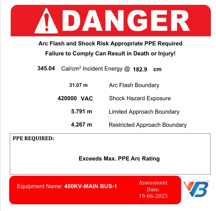
Every figure printed on an arc flash label comes from one row of the report: incident energy at the working distance, arc flash boundary, shock hazard voltage, limited and restricted approach boundaries, the equipment name and the assessment date. If the label on your switchgear cannot be traced back to a row in the incident energy table, the label is an opinion, not a finding. Section 9 of the report is that schedule, and the free review checks it row by row.
Who reads it
Three readers, three different pages
Your insurer or FM Global
Opens at the conformance matrix and the certification page. Wants a named engineer, a date, and the buses above 40 cal/cm² with an action against each.
The inspector
Opens at the label schedule. Checks the four NEC 2026 elements and the assessment date against the panel in front of them.
Your own electricians
Open at the incident energy table and the TCC plots. Need the working distance, the scenario and the PPE category per bus, not a summary.
Why the verdict carries weight
Written by the team that has labelled 12,547 assets
Data centers, pharma, power, oil and gas and process plants in 21 countries. The reviewer has read reports from every vendor type.
IEEE 1584.1-2022 for the deliverable, IEEE 1584-2018 for the method, NFPA 70E and NEC 110.16 for the duty. ETAP and SKM PowerTools.
The engineer who reviews your report puts their name on the verdict. A US-licensed Professional Engineer is available to stamp any study that follows.
UPS strings, battery cabinets and 800 VDC halls sit outside IEEE 1584's AC range. The review checks whether they were studied at all.
The verdict is against the 11 sections, not against VB's proposal. If your report is sound, the verdict says so.
No call unless you ask for one. The verdict is yours to forward, whoever does the work.
Before you ask
Questions before you request the review
What does an arc flash study report contain?
A complete arc flash study report contains 11 sections: a conformance matrix against NFPA 70E 130.5, NEC 110.16 and the client specification; an executive summary; the IEEE 1584-2018 method and assumptions; the as-found one-line diagram; the field data pack; short-circuit results; protective device coordination; the bus-by-bus incident energy table; the label schedule with artwork; the action register; and the certification required by 29 CFR 1910.132(d).
What does IEEE 1584.1-2022 require in an arc flash study deliverable?
IEEE 1584.1-2022 is the guide for the specification of scope and deliverable requirements for an arc flash hazard calculation study. It expects the deliverable to document scope and references, methodology and assumptions, the software used, input data, operating modes, short-circuit and time-current results, a results table per bus, an updated single-line diagram with matching nomenclature, labelling, recommendations, and an advisory on what system changes invalidate the study.
Can I see a sample arc flash study report?
Yes. Request the free review and the VB engineer's reply carries a full sample report for a data center campus, with site, client, drawing numbers and bus names removed, within two business days. Use it as a checklist against the report you hold or against any vendor's proposal. The VB Arc360 brochure on this page opens with one click, no form.
How do I read the incident energy table?
Each row is one bus. Read the voltage, the working distance the figure applies to, the clearing time, the incident energy in cal/cm², the arc flash boundary, the PPE category, and the scenario that produced the worst case. A row with no scenario or no working distance cannot be checked. Above 40 cal/cm² the work is de-energised or not done.
What should the one-line diagram in the report show?
The plant as found on the walkdown, not as drawn years ago: every source, transformer, bus, feeder and protective device with the same names used in the tables, drift from the legacy drawing logged, and the site engineer's co-signature. If the one-line is dated before the walkdown, the calculation used the wrong plant.
How do you tell a strong arc flash report from a weak one?
Four markers: a named engineer signs every section; every input is reconciled to the as-found plant and co-signed; every assumption is declared so each number traces to its source; and the report opens with a conformance matrix so compliance can be verified in under ten minutes. The free review on this page scores your report against all four.
When does an arc flash study report need to be redone?
At least every five years under NFPA 70E 2027 130.5(G), and whenever the electrical system changes: a transformer replaced or re-tapped, new feeders or boards, protective device settings changed, a generator or UPS connected or re-configured. A 2020 report is already outside the window.
Is my existing arc flash report good enough?
Request the free review and find out. A VB practice engineer sends you a secure link for the report, then scores it against the 11 sections, present, partial or missing, and emails a written verdict in two business days, including whether the study can be reused with new labels or must be redone. There is no charge and no obligation.
Does the report cover UPS and battery DC systems?
In a VB report, yes, in the same incident energy table. IEEE 1584-2018 is validated for AC from 208 V to 15 kV, so UPS battery strings, battery cabinets and DC buses are calculated with the DC methods in NFPA 70E Annex D and stated as such. Many reports leave these buses out; the review checks whether yours did.
Who signs the report and does it need a PE stamp?
The engineer of record signs every section, with an independent reviewer. A Professional Engineer's stamp is applied where the state or the client requires it; a US-licensed PE is available for VB studies. The certification page also carries the written hazard assessment certification that 29 CFR 1910.132(d) requires.
Find out what your report is missing before the inspector does.
Request it now. A written verdict against the 11 sections, and a full sample report, in your inbox within two business days. Free, signed, yours to forward.
Review my reportPrefer email? Send the report to connect@groupvb.com with the state in the subject line.